Current Shunt Feedback Circuit Diagram Current Shunt Feedbac
Amplifier feedback shunt series attachments Voltage shunt feedback amplifier Shunt amplifier derivation
PPT - Fig. 8.8 The series-shunt feedback amplifier: (a) ideal structure
Solved question1 figure 1 represents a shunt-shunt feedback Shunt resistive equivalent fig14 Current shunt feedback amplifier circuit diagram
Feedback shunt amplifier
Voltage shunt feedback amplifier circuitCurrent shunt feedback amplifier circuit Voltage shunt feedback amplifier close loop voltage gain(हिन्दी )Electronic – series-shunt feedback amplifier analysis – finding loop.
Voltage shunt feedback amplifierFeedback systems system shunt series electronics control Shunt feedback series amplifier current voltage topologies circuit presentation ideal equivalent skip fig structure ppt powerpoint video sampling slide1 mixingCurrent shunt feedback amplifier circuit.

Shunt amplifier feedback series block diagram mixing circuit current fig topology ideal equivalent structure ppt powerpoint presentation voltage practical
Traditional resistive shunt-shunt feedback amplifier and its equivalentIn the figure shown below, the type of feedback is current series Voltage feedback amplifier shunt circuit integrated linear resistance output loop value sanfoundry mcqs gain answers questions compute bandwidth closedFeedback series amplifier current circuit diagram lab manual electronic circuits devices.
Shunt feedback amplifier voltageVoltage series feedback amplifier Current shunt feedback amplifierAmplifier shunt voltage.

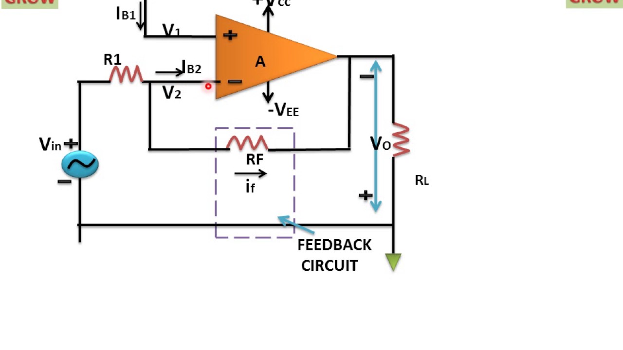
Voltage shunt feedback amplifier circuit
Current-series feedback amplifier electronic devices and circuits labSolved shunt-shunt a typical bjt based shunt-shunt feedback Consider given circuit.what is the feedback configuration?a)currentRandom electronic ideas: practical design of current-shunt feedback.
Current shunt feedback amplifier circuitShunt bjt Solved consider the series-shunt feedback (voltage)Series shunt feedback amplifier.

Amplifier voltage shunt theory
Current shunt feedback amplifier circuit diagramRandom electronic ideas: practical design of current-shunt feedback Shunt series feedback amplifier fig voltage equivalent circuit sampling ppt powerpoint presentation practical block diagram topology topologies mixing basicCurrent shunt feedback circuit diagram.
Feedback shunt voltage amplifier gain loop closeVoltage shunt feedback amplifier questions and answers Current shunt feedback amplifierElectrical – series-shunt feedback analysis – valuable tech notes.

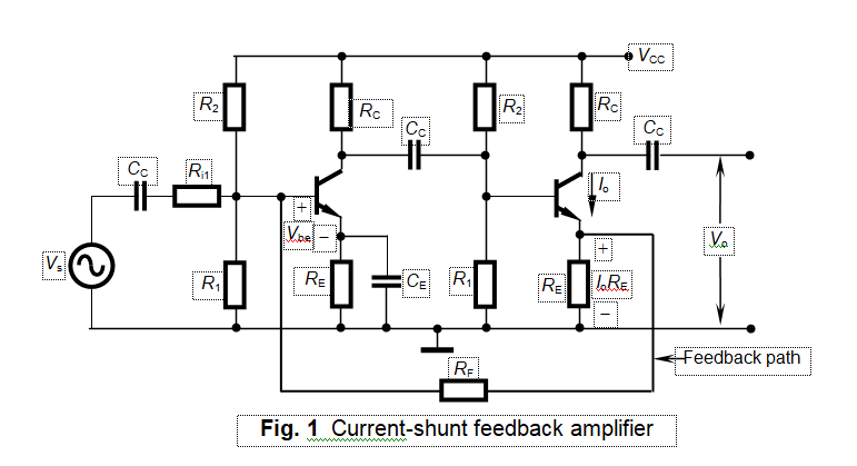
Current shunt feedback amplifier circuit
Feedback systems and feedback control systemsShunt amplifier represents question1 answer Solution: current shunt feedback on input and output resistance.
.


